
Modeling with the standard notation BPMN 2.0
SmartProcess provides you with elements for modeling business processes in accordance with BPMN 2.0 (Business Process Model and Notation). The BPMN 2.0 notation was published by the Object Management Group® (OMG). This page shows process modeling according to BPMN with the SmartProcess software.
The modeling notation BPMN 2.0 is often used for modeling business users to create process models. The BPMN notation is the leading standard for modeling business processes. In addition to the BPMN elements, the BPMN tool SmartProcess also supports extended symbols that are important for modeling business processes.
SmartProcess supports the validation of modeling rules and the import and export of BPMN files with the BPMN elements for business processes shown here.
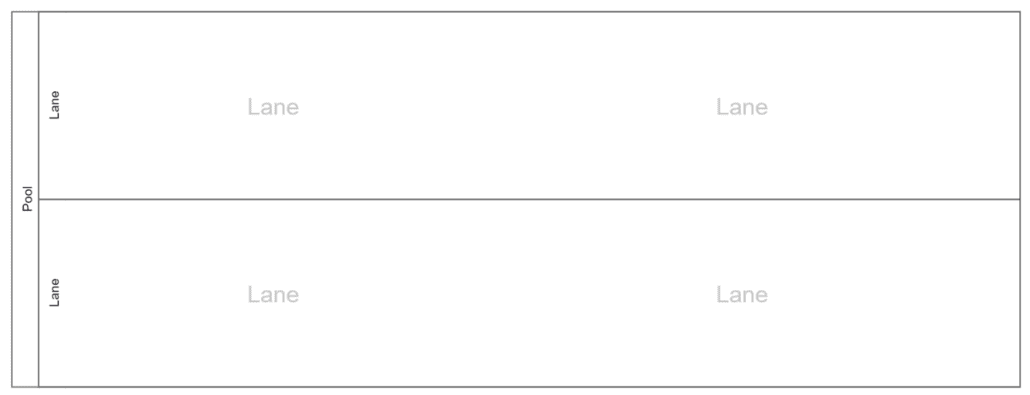
Pools and lanes
In BPMN 2. 0, pools and lanes are used to indicate which organizational unit or role is responsible for performing one or more tasks in the process flow. A lane is a sub-unit of a pool. As a rule, only one pool is included per process. Companies are also presented as a pool.
You can model expanded and collapsed pools in the BPMN tool SmartProcess. You can align pools and lanes horizontally and vertically. A lane is linked to an organizational unit or role in the BPMN software SmartProcess. In the SmartProcess organization chart, you can see exactly who performs which tasks in the company.
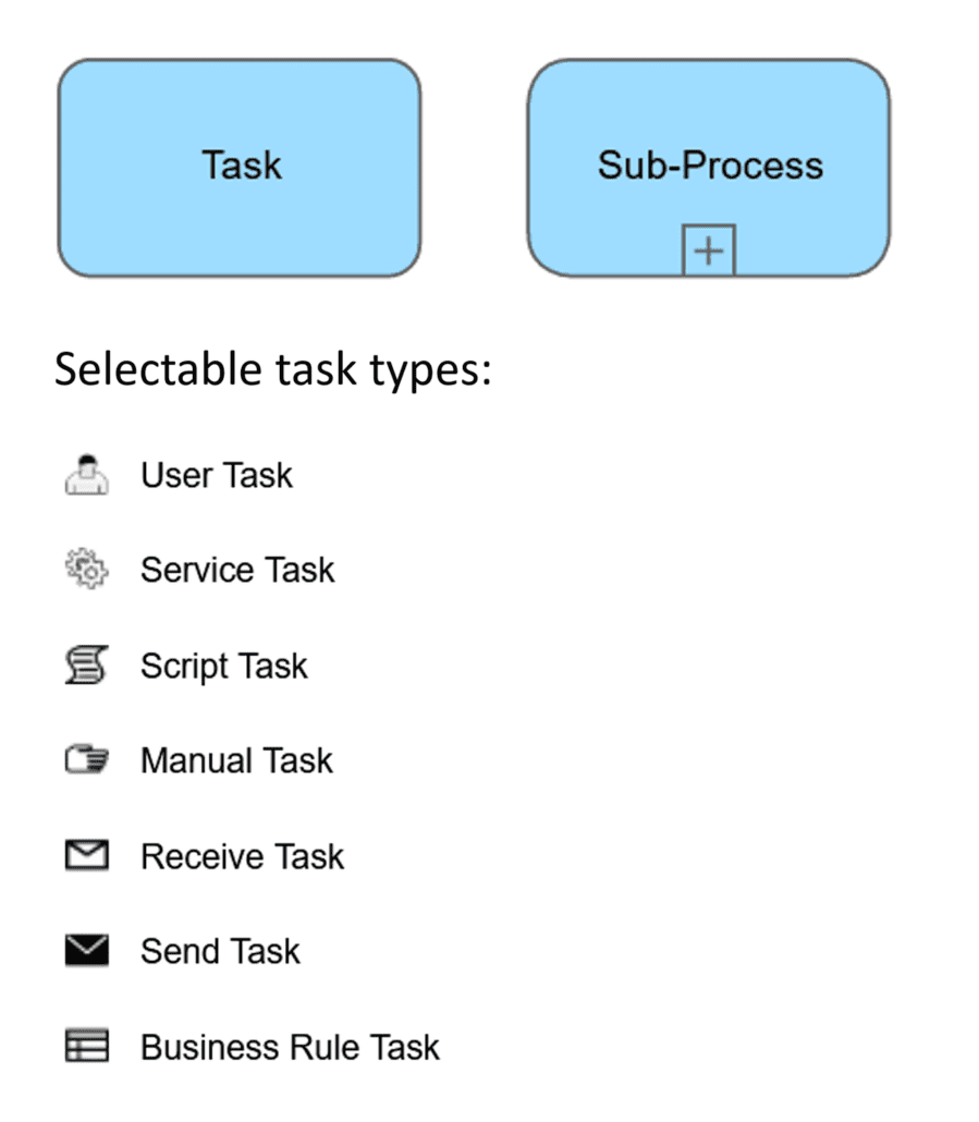
Activities
In a process, the tasks and sub-processes are the main information that describe the actions and activities. A task is a self-contained sub-step of a process.
In a sub-process, related tasks are bundled together in the BPMN software and arranged below a process. The task type can be changed during process modeling in the BPMN software SmartProcess. Initially, a standard task is created in the BPMN tool to enable simple operation. If necessary, the task type of the activity can simply be changed via the context menu in the process model. The corresponding icon is then displayed at the top left of the task.
Events
Each process contains a start event and an end event. The events are used to display the current progress of a process flow. In BPMN 2.0, intermediate events in particular enable a transparent representation of process progress during process modeling.
With the BPMN software SmartProcess, you can create simple and comprehensible process models with a start event, intermediate event and end event.
However, all BPMN 2.0 event types are also available if you need to visualize more complex processes. The user is optimally guided during operation to select the correct symbol from the numerous BPMN symbols.
Gateways
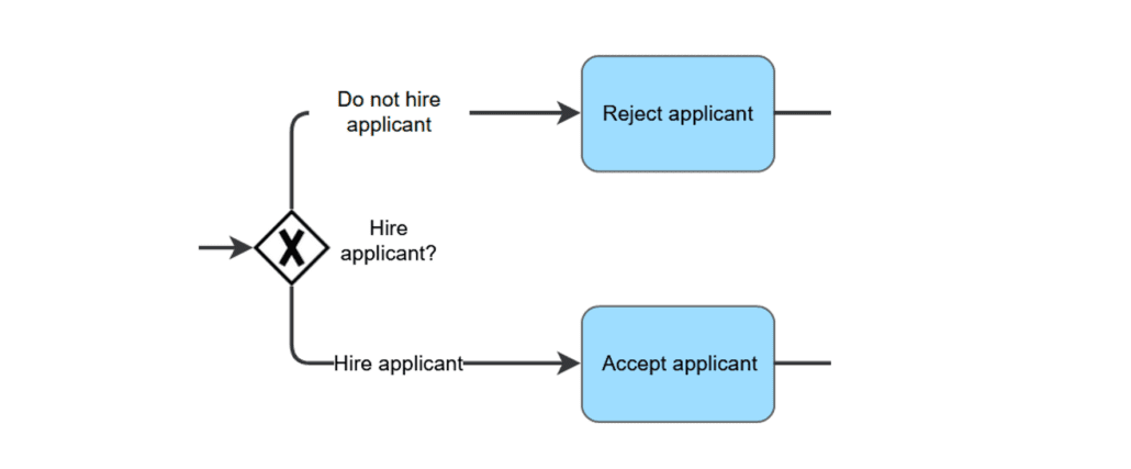
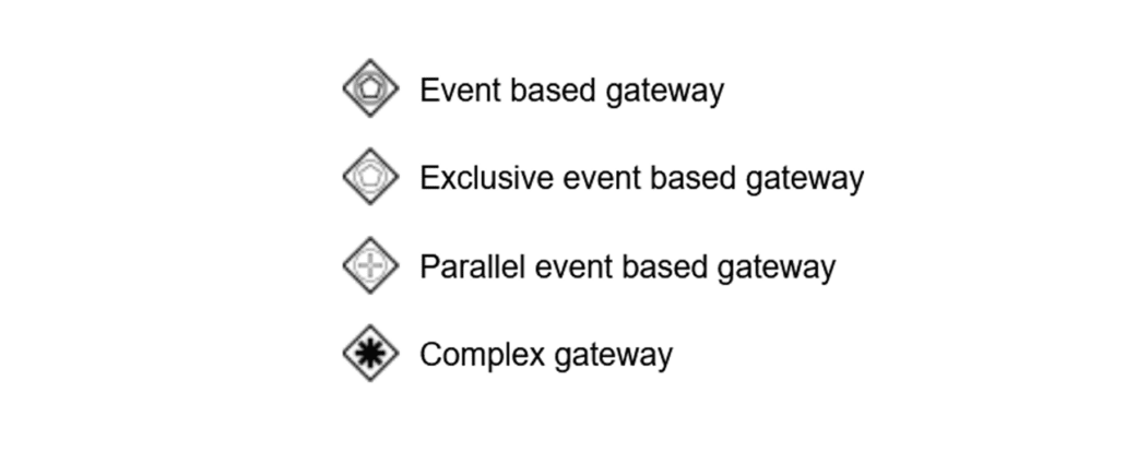
The gateways can control decisions such as an “or” decision and split and merge the sequence flow for parallel activities. In the SmartProcess BPMN tool, the main gateways are displayed directly in the symbol palette. The more advanced and rarely used gateways can be selected as a gateway type via a context menu.
Exclusive gateway
There are any number of possible options for a decision, of which only one can be selected at a time. This means that only one of the outgoing paths is followed and only the tasks modeled behind it are executed.
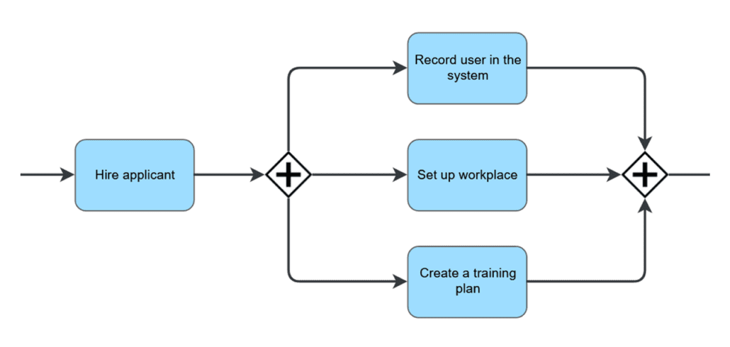
Parallel gateway
All possible options are executed. This means that every possible outgoing path is followed and all the tasks modeled behind it are executed in parallel in the BPMN software.
If the sequence flow is split, a merging gateway is modeled at the end of the simultaneously executed tasks. This indicates that the process flow is only continued once all previously initiated parallel tasks have been completed, i.e. all outgoing paths have been merged again.
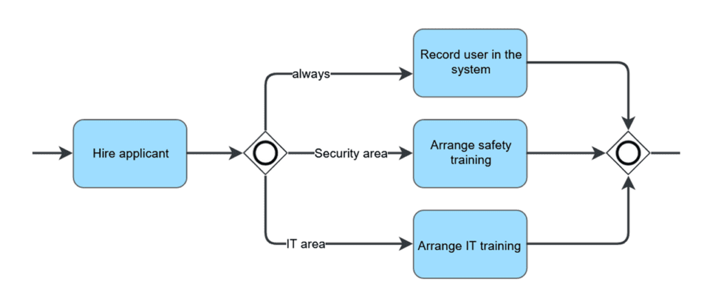
Inclusive gateway
There are any number of possible options for a decision, one or more of which can be selected depending on the condition. As several parallel activities are also possible here, this gateway is also merged again.
Further gateways
In order to use the advanced and rarely used BPMN 2.0 gateways in the BPMN tool, the gateways can be added to the process model as a gateway type by clicking on a main gateway in the context menu.
Data object
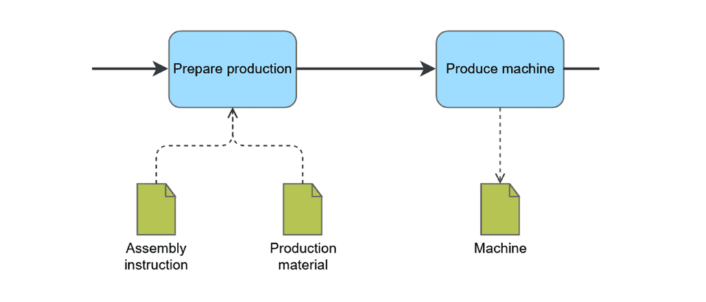
The data objects represent the inputs/outputs for process modeling in the BPMN diagram. In the BPMN tool SmartProcess, interactions between processes can be modeled to show how information is processed across different processes.
Data objects are used in the BPMN 2.0 process notation when an output is generated during the execution of a task in the process, which is reused as input in one or more processes and further processed. Whether it is an input or output can be recognized by the direction of the message flow.
Connector
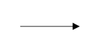
The sequence flow is used in BPMN 2.0 notation to represent the flow of the process from the start event, through the individual tasks to be completed, to the end event.
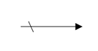
A standard sequence flow is run if the conditions of the other flows are not fulfilled.
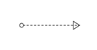
The message flow is used to represent the communication between external units and pools.
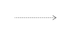
The association link is used to display the reference of additional information such as artifacts to tasks.
Artifacts
The term artifact is used in the BPMN software SmartProcess to summarize several objects in process modelling that can be used to represent additional information for a process or a task in the process.
The proprietary SmartProcess artifacts support the BPMN standard modeling to model meaningful and comprehensible processes. All symbols can be shown and hidden in the settings for the BPMN tool for the process modeler.

The group delineates some selected objects in the BPMN 2.0 notation.
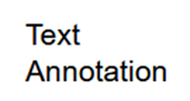
With text annotation, process modelers can easily add text to a BPMN process. The text annotation is linked to an object using the association link.

The artifact key figure is used in the process model to illustrate relationships. Processes can be assessed using key figures. A process or a task in a process influences the value of a company key figure.

The IT system artifact is used in the process model if an IT system is to be used to perform a task or if data is to be stored in a data memory.

The risk artifact is used in the process model to represent interrelationships. The performance of a task may result in a risk for the company. A risk must be taken into account when carrying out a task.

The opportunity artifact is used in the process model to show when opportunities could arise for the company during the execution of a process or task that can be exploited.

The ‘Adjacent process’ object can be used to indicate that a process is preceded or followed by other processes. In this way, for example, the value chain of a company can be represented, which consists of several successive processes.

The artifact Applicable document is used in the process model to indicate that a document is used when carrying out a process or task.
The artifact can be used to open the document directly for the user in the BPMN software.

Applicable documents can be stored in a document folder. If there are a large number of documents in a BPMN process, the documents can be grouped together in the folder to maintain clarity during process modeling.

To represent the participation of an organizational unit or role in an individual task, the modeling object ‘Additional participant’ is suitable. The type of participation, such as implementation, decision, support, advice and information, can also be selected here. Otherwise, the assignment takes place automatically via the lanes in the BPMN tool.

The resource artifact is used in the BPMN process model if a resource is to be used to perform a task. Operating resources can be tangible (machines, tools) or intangible (licenses, patents).

The Hyperlink object can be used to link to any destination. This can be an area in the SmartProcess BPMN software such as the knowledge base or an external website.
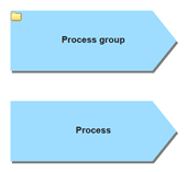
With the process diagram process group, clear process maps can be created with the objects process groups and processes as an extension to the BPMN notation in order to illustrate relationships within the company. The process group object is also used to group and display the processes in the BPMN software SmartProcess in folders in the process explorer.
As it is also possible to navigate through the various process models or flowcharts by clicking on the modeled objects, process groups are suitable for creating interactively clickable process landscapes in the BPMN tool SmartProcess.
When selecting Character symbols, an extensive collection of character symbols is available for display in the BPMN process. In the BPMN tool, you can also insert your own user-defined images into the process model.
BPMN 2.0 objects that are not used
- As every activity can be reused in SmartProcess, the call activity is not marked separately. The transaction and an event sub-process is not used as it is modeled as a collapsed sub-process. Sub-processes are always shown as collapsed objects in process models. Click to open the sub-process clearly in a new window.
- Conversation diagrams and choreography diagrams are not used, as these diagrams are rarely used for modeling business processes.